Sunday, 28 May 2017

The Neo-7M GPS receiver

Photo 1 shows a GPS receiver (the central, blue, board) I recently acquired eBay for less than $10.

The (white) chip in the board-centre is a Neo-7M-000 from uBlox. (There are several other chips in the Neo-family that differ mostly by their type of oscillator. The Neo-7M uses a straight crystal whilst the 7N has an in-built temperature controlled oscillator, for example). 

My receiver came with a passive antenna, but to get a better signal indoors, I swapped it for the active antenna on the right in the photo. 

uBlox have free software on their website that allows you to talk to the GPS module from Windows through USB when you use a USB-to-TTL converter (mine's the red 'CP102' module at the left of the photo; A couple of $'s on eBay). 

It's super-satisfying when you connect things up for the first time and a world-map appears showing you a bunch of orbiting GPS satellites you've locked on to.


Naturally you can read GPS time and location data from your Neo, but (following an idea from the excellent Scullcom hobby electronics site) I was keen to get my hands on a GPS-accurate frequency-source.

This means means soldering a wire (here yellow) to one terminal of a surface-mount resistor on the PCB. Photo 3 below shows the detail


The default setting of the Neo is to spit out a 1Hz square wave on the yellow wire, but the software (under the View/Configuration View/TP5 menu) allows you to change this. I captured the oscilloscope trace below with my Neo output set to a 1MHz square wave


The significance of all this is that, for a few $'s, I now have a GPS ('atomic clock') accurate frequency source! This opens the door to all sorts of fun stuff that relies on an ability to very accurately time events: A homemade experiment to measure the gravitational constant by very accurately timing swings of a pendulum say - or a dozen other things.

If you've  thoughts about that or any of the other stuff on this blog here I'd love to hear your suggestions.

Sunday, 20 November 2016

A 1.8V-safe amplifier

When working with embedded development boards (such as the Beaglebone and the TM4C Launchpad), it's common to need to restrict any voltages you apply to analog-input pins to a 'safe' range (typically less than 1.8V).

Figure 1 shows one way I came up to do this:


The STMicro LF15ABDT is a low dropout voltage regulator: you give it a voltage between 2.5V and 16V and it outputs a fixed 1.5V.  This 1.5V is used to power an MCP6041 op-amp. - a  rail-to-rail amplifier able to run off a supply as low as 1.4V.  The amplifier's output voltage can obviously never get larger that the 1.5V supply.

Here it is for real (the centre board) with the input (in this case a thermistor signal) coming in on the blue wire and going out to my TM4C Launchpad on the white. The flying leads and lack of ground planes etc. means it isn't going to win any prizes for precision analog design (!), but hey, as a quick way to safely feed the Launchpad's sensitive analog inputs, it does the job.


Saturday, 29 October 2016

Constructing Structures at Compile-time in C

In embedded software, it's common to need to pass board-specific configuration data to a function.

In such cases, it's tempting to declare a set of const's (typically structures) to hold all the configuration values .

The downside of this approach is that memory is precious in embedded; d
efining lots of constants, not all of which may be used, is undesirable.

To give a concrete example


Suppose we're writing a library function to start-up a microprocessor's analog-to-digital converter:


fStartADC( pConfigData );

Here pConfigData is a pointer to a C-Structure containing configuration data for the ADC (for example the pin on the board you want the ADC to connect to).

If there are seven (say) possible ADC configurations, its tempting to declare a set of const. structures CONFIG0 ... CONFIG6, for users of your library function.

Should a user only make use of (say) CONFIG3 however, you risk having six unused structures bloating memory.

Instead, you'd like to provide users of your library a set of predefined structures CONFIG0 ... CONFIG6, but have the compiler only create (instantiate) those that the user actually uses.

C++ offers you such things as constructors to help with this. In C it takes a little more work, but here's one way:

To keep things simple, suppose our ADC CONFIG structure needs to hold a single integer, x (in real life, configuring the ADC need require multiple e.g. pin, port, oscillator... etc. values)

First, we declare a type for our structure and a pointer to it.

typedef struct { int x; } ConfigData_t, *pConfigData_t

Next, we define a function that takes an integer, creates a structure containing the integer, and returns a pointer to it.

pConfigStruc_t fConstructor( int x ) {
static ConfigStruc_t CONFIGn;
CONFIGn.x = x;
return &CONFIGn; }


Finally, we define some macro's

#define CONFIG0 ( fConstructor ( 7) )
#define CONFIG1 ( fConstructor (67) )
..etc.


where 7, 67 are examples of board-specific configuration values.

We can now offer users of our library, a set of predefined configurations CONFIG0,CONFIG1 insulating (abstracting) them from any messy details of our board hardware. The user is free to write a line of code like:

fStartADC( CONFIG0 );


At compile-time, in accordance with our #define, the compiler will dutifully replace CONFIG0 with fConstructor(7)

fConstructor (7) will then do its job, returning a pointer to a structure containing '7'.

Notice however, that since our user never wrote CONFIG1, a structure holding 67 was never created!

We've met our goal of providing users with a set of predefined CONIG's  but at the same time made sure that only those they use will be compiled into memory. Neat huh!

To see a 'real world' example of this technique, check-out my gitHub code here

Tuesday, 25 October 2016

Programming the Launchpad UART

Having immersed ourselves in the complexities of CAN recently, communicating by UART is like coming up for air!

UART is dead simple: 
       One wire (plus ground)
       Agree a data (baud) rate data
      ...and start sending 0's and 1's!

(Actually, there are a few other things you can add such as check-bits etc. But we'll ignore these)


The Texas Instruments TM4C123 Launchpad is a low cost ARM micro-controller I introduced here

TI have free software (an API) for UART communication, but I decided to write my own (partly for fun, partly 'cos I wasn't 100% clear about my licence-freedom to show TI's code, and partly 'cos I wanted to use the ARM CMSIS code standard).

My code is here


The functions I've defined do the obvious...

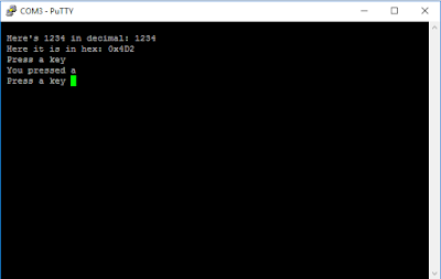
startUART(UART0, UART0_CFG, baud115200) starts a UART.

fprintstringUART(UART0, "blah, blah...") prints a string.

fprintcharUART(UART0, myChar) prints a character ('myChar')

fprintUint32UART(UART0, 32, DEC) prints '32'

fprintUint32UART(UART0, 32, HEX) prints '0x20'

Using a UART monitor such as the awesome PuTTY, UART_example.c results in


The code has limitations:

At present it's limited to baud9600 or baud115200 (see the enum's in uart_helper.h). Also, when starting a UART its necessary to pass in configuration data. You do this by passing the fstartUART() one of the predefined configurations "UARTn_CFG" (my next post, and the comments in uart_helper.h explain how this works). So far I've only gotten around to defining UART0_CFG.


Finally fprintUint32UART() assumes you're doing the right thing passing it an unsigned integer - there's no size checking etc.
The code-flow basically follows the Lauchpad datasheet (DS-TM4C123GH6PM-15842.2741). So, for example, the datasheet tells you on p.902, that if you want to use the UART, the first thing to do is "Enable the UART module using the RCGCUART register"

Hence the line
     SYSCTL->RCGCUART |= RCGCUART_R0;


in my fstartUART() function. Etc.

For those just getting started I gave an intro. to the concept of registers here

For those unfamiliar with "->" notation, this comes from the so-called "ARM CMSIS". This is a standard way to talk to ARM chips. More about this another time.

Definitions of all the Launchpad's registers (RCGCUART etc. etc. ) are held in a board file (here TM4C123GH6PM.h) you can download from TI. I couldn't find a file listing the individual register-bit-fields however (anyone?) so I started my own tm4c_register_fields.h.

That's all for today. If you spot bugs (there are bound to be some!) or just have a comment generally, drop me a line.

Monday, 24 October 2016

CAN Bus Project Part 8 : Summary

This is Part 8 in my project to send data from my Arduino (/Genuino) to my TI Launchpad.

It's time to summarize. Here's my setup:


- In Part 2 we connected the Arduino to a thermistor.

- Part 3 connected the Arduino an MCP2515 CAN Controller.

- Parts 6,7 connected a TI Launchpad to a MCP2551 to receive CAN data.

Part 5 gave a CAN overview.

All the code is on my github page.

I didn't describe the Launchpad thermometer icon I created using the TI's "GUI Composer". 


To create it I followed some TI "GUI Composer" instruction videos. You simply select icons (here I chose a thermometer and text box) and tell GUI Composer what variable(s) you want the icon to display - in my case g_ui32MsgCount and g_temperature in the Part 7 code. 

I also didn't describe setting up the Launchpad vector table. I'll do a more detailed post about vector tables in future. For now, for those of familiar with such things you simply need to tell the CAN0 interrupt to call CANIntHandler().

Leave a comment  and enjoy!

Thursday, 20 October 2016

Chip Chat No.2 - A low cost function generator


I recently stumbled across a function generator kit on Amazon. On the basis that an electronics ‘den’ can never have too many frequency sources, I ordered one. 

For around $10 you get a pre-drilled PCB, a bag of components and a basic enclosure. Photo 1 shows the end result once I’d soldered it together.

The kit instructions are pretty basic and it helps to have a ohm-meter to check resistor values etc. as you go along. Overall however, things are clear enough.

You need to supply the board with between 9V and 12V (the datasheet warns of instability above 12V). The first thing I did was to plug in a supply of the wrong polarity, “popping” one of electrolytic cap’s and frying the IC. Grrrrr! Fortunately both were cheap to replace.

The board is based around an Exar Corporation XR2206 Monolithic Function Generator IC. The chip datasheet describes applications of this chip as function generators (it’s role here) and communication instrumentation (in particular FSK applications; more about this another time). The XR2206 comprises a voltage controlled oscillator (VCO) oscillating at a frequency set by an external resistor + capacitor. On the board, this resistor is a couple of pots. A row of jumpers allows you to change the capacitor range. On-chip wave-shaping allows you to output a square, triangle or sine wave.

As you’d expect for the price, there are limits to the quality of the output waveforms: On the up-side, you can generate waves from a few Hz to 1MHz. Adjusting frequency and amplitude is as easy as twiddling the knobs. Using these I was able to adjust frequencies to within a few 10th's of a %.

On the downside, the datasheet advises you’re limited to 0.5% sine wave distortion with a maximum amplitude variation of  4800 ppm/degC, set partly by external resistors. The DC value of the output waveforms is centred around 50% of your power rails and I found the sine- and triangle waves began to clip around 4Vp-p. The square wave amplitude isn't adjustable. Finally, I noticed some peak-to-peak amplitude asymmetry (especially at low frequency). 

As every electronics designer knows, there are times when you need precision. Other times however, you just need some waveform and desperately don’t want to have to wait a week for your £5000 function-generator software to boot! You’re not going to be running your atomic-clock off this baby, but overall I’m happy with what I got for my $10.

Finally, for those interested, here're some of the output waveforms: 

1kHz sine 


From here on I switched the oscilloscope to AC coupling.
1kHz triangle...


1kHz square...


1kHz sine starting to clip above 4Vp-p...


600kHz Sine...


10Hz sine...

Monday, 17 October 2016

Chip Chat No.1 - a protoboard power supply

A short post today to mention a handy little board you might appreciate having in your tool kit.

The photo shows a 'YuRobot' board (I've no connection with the company) I picked off ebay recently for a couple of quid (that's 'bucks' to my US readers).  


It has pins on the underside which plug into a prototyping breadboard, creating two sets of breadboard power rails. The little yellow jumpers allow you select 3.3V or 5V outputs.

You supply power to the YuRobot through a 9V supply (the datasheet for the voltage regulators say they have a 15V absolute max.) or from your PC's USB port (you'll need a male-to-male USB cable).

The board features a couple of AMS1117 voltage regulators in SOT-223 packages. The AMS1117 datasheet says these are rated to 1A, with an output voltage accurate to 1.5%. My voltmeter measured 3.296V and 5.015V - pretty good for the price.

Overall, a handy little widget I can recommend.